Description

How Cryogenic Recovery Works
The principle is straightforward: as gas temperature drops, vapour pressure drops with it. Pass a VOC-laden stream through a series of cold heat exchangers cooled by boiling liquid nitrogen at −196 °C, and the volatile components condense — first to liquid, then to solid — leaving a clean gas to vent.
Ever-power’s design uses a separate, sealed nitrogen circuit so the LN2 never contacts the process stream. This means recovered solvent is uncontaminated by nitrogen, and the warmed gaseous nitrogen leaving the cold-box is clean enough for downstream blanketing, purging or pressure transfer — effectively giving the operator two utilities from one consumable.
Why Cryogenic Recovery Beats Alternatives for High-Value Streams
| Criterion | LN2 Cryogenic | Activated Carbon | Thermal Oxidiser |
|---|---|---|---|
| Recovers solvent for reuse | Yes — near 100% | Partially (steam regen) | No — destroys |
| Best at high concentration | Yes | Difficult / unsafe | Yes |
| Outlet level | Down to single-digit ppm | Low ppm (when fresh) | Low ppm |
| Fire/explosion risk | Inert nitrogen stream — very low | Bed fire risk on ketones & styrene | Hot oxidation — managed risk |
| CO₂ emission footprint | Very low — no combustion | Low (steam-driven) | High — assist fuel |
| OPEX driver | LN2 supply (offset by reuse) | Steam + carbon replacement | Fuel gas |
| ATEX-zone install | Yes — no ignition source | Special precautions | Engineered safety case |
System Design Highlights
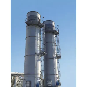
Multi-Stage Condensation
Three-stage cooling profile — pre-cooler (~+5 °C), intermediate stage (~−40 °C) and deep cryogenic stage (down to −130 °C). This staged approach cuts total LN2 duty by 12–16% versus a single-stage equivalent and prevents premature freeze-out at the inlet.
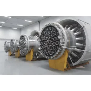
Finned-Coil Cryogenic Exchangers
Engineered finned-coil heat exchangers with internal flow conditioners maximise surface area and enable rapid response to flow-rate peaks — essential when batch processes generate spiky vent streams.
Sealed Nitrogen Circuit
LN2 boils inside a separate pressurised circuit and never touches the VOC stream. Recovered solvent is uncontaminated; warmed gaseous nitrogen exits clean and is immediately usable for blanketing, purging and pressure transfer.
High Automation
PLC-driven LN2 injection control matches outlet temperature to the target ppm specification automatically — consistent compliance even with feed concentration swings, and minimal operator intervention.
Multi-Solvent Capability
A single cryogenic skid can address mixed-solvent streams — alcohols, ketones, halogenated hydrocarbons, BTEX and aromatics — without the bed-replacement cost of activated carbon.
Environmental Reporting
Integrated carbon-emission monitoring and energy-saving instrumentation feed your NGER and Scope 1/2 reports directly — the data is captured, not retrofitted.
Operating Specifications
| Parameter | Specification |
|---|---|
| VOC recovery efficiency | Up to 99% (single solvent), 95%+ (mixed) |
| Outlet VOC concentration | Single-digit to low double-digit ppm |
| Inlet flow range | 50–5,000 Nm³/h (low-to-medium flow) |
| Inlet concentration | 10 g/Nm³ to saturated |
| Cooling medium | Liquid nitrogen at −196 °C, sealed circuit |
| Stage temperatures | +5 °C / −40 °C / −130 °C (typical) |
| Recovered solvent quality | Re-usable, uncontaminated by N₂ |
| Nitrogen reuse | Clean GAN for blanketing/inerting |
| Hazardous area | Suitable for ATEX Zone 1 / Zone 2 |
| Compliance | AS 1940, AS 4041, AS/NZS 60079, NEPM |
Best-Fit Applications
- Pharmaceutical & API manufacturing: recover acetone, methanol, ethyl acetate, dichloromethane and toluene from reactor and dryer vents — turn waste into reusable solvent inventory.
- Petroleum loading terminals: petrol vapour recovery during ship, rail and truck loading where recovered hydrocarbon is returned directly to the storage system.
- Specialty chemicals & coatings: resin, ink and adhesive plants with concentrated solvent vents that an RTO would burn at significant cost.
- Polymers & rubbers: monomer recovery from polymerisation vents — styrene, vinyl chloride, butadiene.
- Fragrance & flavour: recover and reuse expensive aromatic compounds without thermal degradation.
- LNG and gas-processing satellite plants: end-flash gas recovery and BOG management.
Why Choose Ever-power for Cryogenic Recovery
You can review our full credentials on the company page, or browse complementary thermal-oxidation technologies via the main site. For a cryogenic recovery decision specifically:
Process & Cryogenic Engineering Under One Roof
Heat-transfer modelling, two-phase flow analysis, ATEX zoning and PLC programming are all in-house — no sub-contracting risk on a system where the cold-box and the controls have to work as one.
Recovered Solvent ROI Modelling
We will model the payback case based on your real solvent purchase price, vent rate and operating hours. For high-value streams, the LN2 cost is regularly offset within 18–36 months.
Australian LN2 Supply Networks
Designs are pre-aligned with major Australian industrial gas supply networks for predictable LN2 delivery to metro and regional sites alike.
Sustainability Story for Your Board
No combustion, no NOx, no SOx, recovered product reused on site — we provide the carbon-equivalent saving calculation for ESG and NGER reporting.
Australian Project Highlights
Pharmaceutical API Plant Cryogenic Recovery
Location: Melbourne, Victoria | Year: 2024
An API manufacturer was burning roughly 180 tonnes per year of recoverable methanol and ethyl acetate in an RTO. Ever-power supplied a three-stage LN2 cryogenic skid that captured 96.4% of the solvent for direct reuse in the process, eliminated the RTO fuel-gas cost and cut Scope 1 emissions by approximately 540 tCO₂e per year.
Outcome: Project payback achieved at 22 months. EPA Victoria licence updated to reflect new emission profile.
WA Petrol Terminal Vapour Recovery
Location: Perth, Western Australia | Year: 2025
A truck loading rack vent stream of approximately 2,400 Nm³/h was treated with a two-stage cryogenic recovery skid. Recovered hydrocarbon was returned to the storage tanks, and outlet VOC was held below 5 mg/Nm³ across full loading and idle conditions.
Outcome: Estimated 240 tonnes/year of petrol fraction returned to inventory. Compliance with the site’s revised air-emission licence achieved at first audit.
Frequently Asked Questions
Recover Your Solvent. Recover Your Margin.
Send us your vent flow, solvent composition, target outlet ppm and operating hours. You will receive a sized cryogenic recovery configuration, payback model and indicative pricing within five working days — the difference between burning value and banking it.