Description
What Is an FCC Waste Heat Boiler?
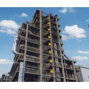
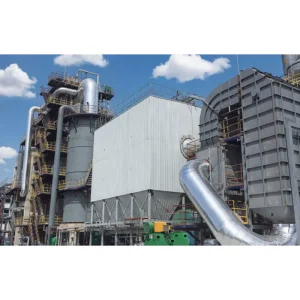
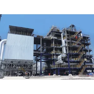
The Ever-power FCC waste heat boiler is a purpose-built heat recovery unit that captures thermal energy from the regenerator flue gas of a fluid catalytic cracking unit (FCCU). Inside a partial-burn FCCU, regenerator off-gas leaves at 650–760 °C carrying significant carbon monoxide, plus catalyst fines, SOx and NOx. The waste heat boiler — often configured as a CO boiler with a supplementary burner — burns off the remaining CO to below 100 ppm and converts the released sensible and combustion heat into high-pressure superheated steam.
This is one of the largest single energy-recovery opportunities inside a modern Australian refinery. A 3 Mt/yr FCCU can produce 150 t/h or more of 9.8 MPa / 510 °C steam, feeding refinery-wide headers, driving compressors and turbines, or exporting to a neighbouring petrochemical complex. When correctly integrated with a flue gas expander and third-stage separator, the whole power recovery train earns back capital in a handful of years.
Ever-power supplies the CO boiler, economiser, superheater, soot-blower island and auxiliary firing skid as an integrated package. The design philosophy pairs FCC-specific process know-how with the same Class A pressure-part manufacturing discipline used across the company’s waste liquid incinerator and industrial boiler lines — built for 200,000-hour service life in an abrasive, acid-dew-prone environment.

Refinery Integration Points
FCCU Regenerator
Partial-burn, full-burn and high-severity regenerators all covered. Design accommodates 650–760 °C inlet with 1.5–4 vol% CO.
Third-Stage Separator
Tie-in downstream of flue gas expander third-stage cyclones. Erosion allowance on leading-edge tubes sized for residual fines load.
Flue Gas Expander
Pressure letdown coordinated with expander trip logic. Boiler pressure envelope matched to expander swallowing capacity.
Main Air Blower
Auxiliary firing interlocks prevent CO afterburn during blower upset. Safety instrumented function (SIF) rated to SIL 2.
Refinery Steam Header
Steam at 9.8 MPa / 510 °C tied into HP header with pressure control, superheat attemperation and bypass letdown for upset recovery.
Flue Gas Treatment Island
Wet gas scrubber, SCR or dry sorbent injection coordinated with boiler outlet. NOx and SOx held within state EPA limits.
How the FCC Waste Heat Boiler Works
Five engineered stages take regenerator flue gas from the FCCU to a compliant stack while extracting maximum enthalpy into refinery-grade steam.
Flue Gas Inlet & CO Fuel Addition
Regenerator flue gas enters at 650–760 °C with residual CO, unburnt hydrocarbons and fines. A refinery-fuel-gas auxiliary burner sustains temperature during low-CO operation.
CO Burnout Chamber
CO is completely oxidised to CO₂ at ≥ 980 °C with staged air addition. Turbulent residence time is engineered at 1.0 s minimum, holding exit CO below 100 ppm.
Radiant Evaporator
Membrane water walls absorb radiant heat. Gas temperature drops from ~1,050 °C to 600 °C. Natural circulation carries steam to an external drum.
Superheater & Convective Bank
Two-stage pendant superheater lifts steam temperature to 485–540 °C. Attemperator trim holds header temperature to refinery tolerance.
Economiser & Stack
Feedwater is preheated against flue gas cooled to 180–220 °C. Downstream SCR or wet scrubber takes over for final polishing.
Key Features & Engineering Advantages
Engineered CO Burnout
Chamber sized to 1.0 s residence time at ≥ 980 °C. CO reliably held below 100 ppm at all FCCU load points — even 70% turn-down.
Erosion-Resistant Tube Design
Leading-edge sacrificial shields, flow-conditioning vanes and low gas velocity on first bank tube — field-proven to 15+ year service life on catalyst fines.
Natural Circulation Evaporator
No circulation pump, no single point of failure on the water side. Steam drum internals handle upset-grade feedwater without carry-over.
Auxiliary Firing & Start-Up Burner
Refinery fuel gas burner rated for cold start through to full-burn mode operation — keeps the boiler online when the FCCU trips.
SIL-2 Safety Instrumented System
CO-afterburn and high-tube-metal-temperature trips engineered to SIL-2 with full FMEA — the documentation your refinery safety team will actually want.
Turn-Key EPC Option
Available as a bolt-on upgrade or a full replacement of existing FCC waste heat boiler — including civils, erection and commissioning on Australian refinery sites.
Technical Specifications
Capacity bands below align to typical Australian and regional refinery FCCU throughputs. Every unit is ultimately sized to the specific regenerator flue gas composition, temperature and pressure envelope of the host refinery.
| Model | Steam Output (t/h) | Steam Pressure (MPa) | Steam Temp. (°C) | FCCU Throughput (Mt/yr, indicative) | Efficiency |
|---|---|---|---|---|---|
| EP-FCC-20 | 20 | 3.82 | 450 | 0.4 | ≥ 90% |
| EP-FCC-50 | 50 | 5.3 | 485 | 1.0 | ≥ 91% |
| EP-FCC-100 | 100 | 9.8 | 510 | 2.0 | ≥ 91% |
| EP-FCC-150 | 150 | 9.8 | 525 | 3.0 | ≥ 92% |
| EP-FCC-200 | 200 | 13.7 | 540 | 4.0+ | ≥ 92% |
Performance & Compliance
| Parameter | Ever-power Guarantee | Reference Standard |
|---|---|---|
| CO at Boiler Outlet | < 100 ppm | US EPA 40 CFR 60 Subpart J |
| NOx (without SCR) | < 180 mg/Nm³ | NSW POEO |
| SO₂ (with SOx additive) | < 150 mg/Nm³ | VIC EPA |
| Particulates | < 30 mg/Nm³ | QLD DES |
| Design Life | 200,000 h / 25 yr | EN 12952-3 |
| Pressure Code | ASME Section I + U stamp | AS/NZS 3788 |
Applications Across Australian Refining & Petrochemical Industry
Fuels Refineries
Standard FCCU heat recovery for gasoline-propylene-petrochemical refineries. HP steam exported to turbines and feed compressors.
Residue FCC (RFCC)
High-coke-yield RFCC units requiring robust erosion design and dedicated SOx/NOx abatement.
High-Severity FCC
Propylene-maximising FCCU with high regenerator temperature — boiler designed to 820 °C peak inlet.
Revamp & Debottleneck
Drop-in replacement where an ageing CO boiler limits FCCU throughput or fails current emission standards.
Combined with Expander Train
Integration with flue gas expander and third-stage separator for maximum power recovery scheme efficiency.
Petrochemical Complexes
HP steam export to adjacent ethylene, aromatics and polyolefin plants through site-wide steam and power utility.
Why Choose Ever-power
An FCC waste heat boiler is not a place for catalogue engineering. A single erosion hotspot in a 9.8 MPa tube bank becomes a full FCCU shutdown. These six engineering commitments separate the Ever-power build from a generic replacement of imported CO boiler.
Our refinery engineering credentials and FCC boiler reference list are on the Ever-power company page, and the full waste liquid incinerator and boiler range is on the home page.
Australian & Asia-Pacific Project Case Studies
Refinery Capacity Revamp — Brisbane Region
A major Australian fuels refinery was planning a 10% FCCU throughput uplift but the existing CO boiler was limiting the regenerator air balance. Emissions stack testing had also flagged a rising CO baseline, with the state regulator putting the site on notice.
Ever-power solution: EP-FCC-100 waste heat boiler package with new CO burnout chamber and downstream SCR tie-in. Engineered to bolt onto existing regenerator duct with minimal piping rework.
Result: FCCU throughput increased 11%. CO stack concentration reduced from ~420 ppm to < 60 ppm. Additional 24 t/h HP steam exported to refinery-wide header.
Petrochemical Complex — Geelong Industrial Corridor
A petrochemical complex was operating a 1980s-vintage FCC waste heat boiler with a rising tube leak frequency and failing acceptance tests on CO emissions. The owner wanted a retubed unit first and a complete replacement if the retube failed technical review.
Ever-power solution: Full replacement of legacy CO boiler with EP-FCC-150 package. CFD-sized CO chamber, Alloy 625 overlay on first-bank tubes, SIL-2 safety system, turnaround-delivered in 28 days.
Result: Acceptance test CO 34 ppm, NOx 142 mg/Nm³. Tube leak history reset to zero through first 18 months. Steam production lifted 12% versus predecessor unit.
Frequently Asked Questions
What is the difference between a CO boiler and an FCC waste heat boiler?
A CO boiler is built primarily to complete CO oxidation downstream of a partial-burn FCCU regenerator, capturing residual heat as a secondary benefit. An FCC waste heat boiler is a broader term covering both CO-burnout duty and pure heat-recovery duty on a full-burn or high-severity FCCU. In practice, the Ever-power package handles both roles on the same pressure envelope.
How is the boiler protected from catalyst fines erosion?
Four lines of defence. First, velocity is capped below 15 m/s in tube bundles. Second, sacrificial erosion shields are fitted on leading-edge tubes. Third, flow-conditioning vanes break up stratified dust-laden streams at inlet. Fourth, tubes in the hottest-dustiest region are specified in Alloy 625 or 800HT. Combined, this has delivered 15+ year tube life on FCCU duty in field-verified installations.
What happens if the FCCU trips while the boiler is running?
The auxiliary firing burner transitions from trim duty to main duty within seconds, holding boiler drum level and steam header pressure. Control logic sits on the site DCS with a SIL-2 backup. This keeps the refinery-wide steam header stable through a brief FCCU excursion and avoids cascading unit trips.
Can the unit be installed during a standard refinery turnaround?
For a retube or partial replacement, yes — we routinely plan around a 35–45 day turnaround window. A full CO boiler replacement is typically staged over two adjacent turnarounds, with civil works and structural steel between them, then pressure-part swap in the second T/A. Critical-path logic is shared at FEED stage.
What NOx abatement is possible without an SCR?
Staged CO burnout, low-NOx auxiliary burners, flue gas recirculation and optional SNCR deliver < 180 mg/Nm³ NOx across most FCCU feed slates. SCR is added where the refinery’s state EPA licence calls for < 100 mg/Nm³ or where nearby sensitive receptors drive a tighter permit. The boiler is designed with SCR hooks regardless, so retrofit is straightforward.
Can the design accommodate future FCCU throughput uplift?
Yes. Design margin on furnace volume, tube bundles, drum sizing and feedwater system can be built in at FEED for a 10–15% future uplift without an oversized day-one footprint penalty. Most Australian clients build this margin in. We document the uplift envelope in the final design basis so future revamps are straightforward.
How long does a full project take from FEED to steam-on?
FEED typically 3–4 months, detailed engineering 6–8 months, fabrication 10–14 months, site erection 5–7 months, commissioning 2–3 months. A realistic total programme is 26–36 months for a full new-build CO boiler on a brownfield refinery — faster on a direct retube or modular replacement.
Need an FCC Waste Heat Boiler Feasibility Study?
Send your FCCU regenerator flue gas data, steam header specifications and site constraints to [email protected] or use the contact page. A feasibility study, CFD-based design concept and budget price will be returned within 15 working days — free of charge.